Feedback Amplifier
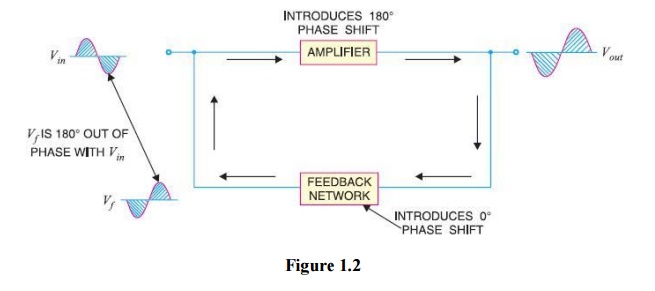
Table of Contents
Feedback Amplifier
A practical Amplifier has an output that is one million times the input, or a gain of almost one million. As a result, even a minor input Disturbance will Manifest itself in Amplified form at the output. Amplifiers have a strong Propensity to introduce hum as a result of abrupt temperature changes or errant Magnetic and electric fields. As a result, the output of every high gain Amplifier Typically Contains both noise and signal.
It is necessary to Minimise the noise in an Amplifier’s output because it is Unwelcome. Through the use of negative Feedback, which Involves Injecting a portion of the output in phase Opposition to the input signal, the noise level in Amplifiers can be Significantly reduced. This Chapter’s goal is to examine the results and Strategies for Supplying negative Feedback to Transistor Amplifiers.
Feedback Amplifier
Feedback is the process of returning a portion of a Device’s output energy to the input. The idea behind Feedback is likely as old as the first machine, but it wasn’t until about 50 years ago that Feedback started to be used in Relation to electronic Circuits. It has been discovered to be very helpful in Lowering Amplifier noise and Stabilising Amplifier operation. There are two basic types of Feedback in Amplifiers: positive Feedback and negative Feedback. These depend on whether the Feedback energy supports or counters the input signal.
(i) Positive Feedback Amplifier –
Positive Feedback Amplifier is used when the Feedback energy (voltage or current) is in phase with the input signal and helps it as a result. Fig. 1.1 provides an Illustration of this. A 180° phase shift is introduced by the Feedback network and Amplifier both. The Feedback voltage Vf becomes in phase with the input signal Vin as a result of the 360° phase shift that occurs around the loop.
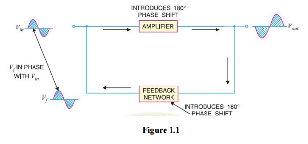
The gain of the Amplifier is Increased by the positive Feedback. However, it has Drawbacks like Increased Instability and Distortion. Therefore, Amplifiers rarely use positive Feedback. In Oscillators, positive Feedback is Utilised Extensively. As we’ll see in the following chapter, Oscillations result from positive Feedback that is Sufficiently strong. In Actuality, a device called an Oscillator Transforms d.c. power into a.c. power of any desired Frequency.
(ii) Negative Feedback Amplifier –
When the Feedback energy (voltage or current) is out of phase with the input signal and thus opposes it, it is called negative Feedback. This is Illustrated in Fig. 1.2. As you can see, the Amplifier introduces a phase shift of 180° into the circuit while the Feedback network is so designed that it introduces no phase shift (i.e., 0° phase shift). The result is that the Feedback voltage Vf is 180° out of phase with the input signal Vin.
Negative Feedback reduces the gain of the Amplifier. However, the advantages of negative Feedback are: Reduction in Distortion, Stability in gain, Increased bandwidth and Improved input and output Impedances. It is due to these advantages that negative Feedback is Frequently employed in Amplifiers.
Principle of Negative Voltage Feedback Amplifier
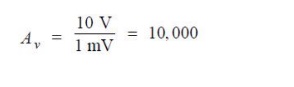
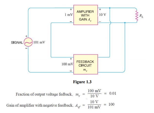
An Amplifier and a Feedback circuit make up a Feedback Amplifier. A portion of the output energy is usually fed back into the input through the Feedback circuit, which is Typically made up of Resistors. The Fundamentals of negative voltage Feedback in an Amplifier are Illustrated in Fig. 1.3*. To make the treatment more Illustrative, typical values have been made an Assumption. The Amplifier’s output is 10 V. The 100 mV portion of this output, which serves as Feedback, is applied in series with the 101 mV input signal at the input. Only 1 mV is seen at the Amplifier’s input Terminals because the Feedback is negative. Gain of Amplifier without Feedback is shown in Fig. 1.3.
The following points are worth noting :
When negative voltage Feedback is applied, the gain of the Amplifier is reduced. Thus, the gain of above Amplifier without Feedback is 10,000 whereas with negative Feedback, it is only 100.
The voltage that is actually applied to the Amplifier when negative voltage Feedback is used is very little. In this instance, the Amplifier’s input voltage is only 1 mV because the Amplifier’s negative Feedback voltage is 100 mV and the signal voltage is 101 mV.
In a negative voltage Feedback circuit, the Feedback Fraction mv is always between 0 and 1.
Gain without Feedback is referred to as Open-loop gain, whereas gain with Feedback is sometimes referred to as Closed-loop gain. These terms refer to the Loop-like structure that Amplifier and Feedback Circuits create. The Amplifier’s gain is Av, or the Open-loop gain, when the loop is opened by Severing the Feedback circuit from the input.
When the loop is closed by Connecting the Feedback circuit, the gain Decreases to Avf , the Closed-loop‖ gain.
Gain of Negative Voltage Feedback Amplifier
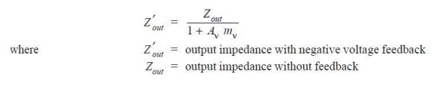
Consider the negative voltage Feedback Amplifier shown in Fig. . The gain of the Amplifier without Feedback is Av. Negative Feedback is then applied by feeding a Fraction mv of the output voltage e0 back to Amplifier input. Therefore, the actual input to the Amplifier is the signal voltage eg minus Feedback voltage mv e0 i.e.,
Actual input to Amplifier = eg − mv e0
The output e0 must be equal to the input voltage eg − mv e0 Multiplied by gain Av of
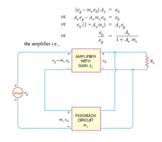
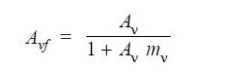
But e0/eg is the voltage gain of the Amplifier with Feedback. Voltage gain with negative Feedback is
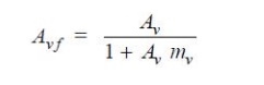
As can be seen, the Amplifier’s gain in the absence of Feedback is Av. However, the gain is Decreased by a factor of 1 + Av mv when negative voltage Feedback is used. It should be noted that negative voltage Feedback has no impact on the Circuit’s current gain.
Advantages of Negative Voltage Feedback Amplifier
The following are the advantages of negative voltage feedback in amplifiers :
(i) Gain Stability–
Negative voltage Feedback has the significant benefit of Enabling the Amplifier’s gain to be Independently controlled by supply voltage Variations and Transistor Parameters.
In order for negative voltage feed-back to work in an amplifier, the designer purposefully set the product Av mv much higher than unity. As a result, in the relationship described above, 1 can be disregarded in comparison to Av mv, and the expression becomes

As can be seen, the gain now only depends on the feedback fraction, or the properties of the feedback circuit, mv. Feedback circuits typically consist of a voltage divider (a resistive network), which makes them immune to changes in temperature, transistor parameter variations, and frequency. As a result, the amplifier’s gain is very consistent.
(ii) Reduces Non-linear Distortion-
A large signal stage has non-linear distortion because its voltage gain changes at various points in the cycle. The negative voltage feedback reduces the nonlinear distortion in large signal amplifiers. It can be proved mathematically that :

It is clear that by applying negative voltage feedback to an amplifier, distortion is reduced by a factor 1 + Av mv.
(iii) Improves Frequency response-
The voltage gain of the amplifier is *independent of signal frequency because feedback is typically obtained through a resistive network. As a result, the amplifier’s voltage gain will be essentially constant over a broad range of signal frequencies. Therefore, the amplifier’s frequency response is improved by the negative voltage feedback.
(iv) Increases circuit Stability-
Variations in the temperature, frequency, and signal strength can easily alter the output of a typical amplifier. This alters the amplifier’s gain, which causes distortion. However, the voltage gain of the amplifier is stabilised or precisely fixed in value by using negative voltage feedback.
This has a simple explanation. Imagine that a temperature change or some other factor has caused a negative voltage feedback amplifier’s output to rise. As feedback is being provided based on the output, this means there will be more negative feedback. This tends to keep the amplification stable and resists growth. If the output voltage falls, the same holds true. As a result, the circuit stability is significantly improved.
(v) Increases input Impedance and Decreases output Impedance-
The amplifier’s input and output impedances are raised and lowered, respectively, by negative voltage feedback. The amplifier can then be used for impedance matching, making such a change profitable in real-world applications.
(a) Input impedance
The increase in input impedance with negative voltage feedback can be explained by referring to Fig. 13.5. Suppose the input impedance of the amplifier is Zin without feedback and Z ′in with negative feedback. Let us further assume that input current is i1. Referring to Fig. 13.5, we have,
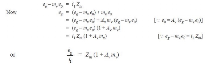
But eg/i1 = Z ′i n , the input impedance of the amplifier with negative voltage feedback.
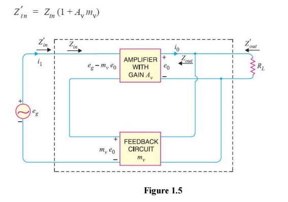
It is clear that by applying negative voltage feedback, the input impedance of the amplifier is increased by a factor 1 + Aν mv. As Aν mv is much greater than unity, therefore, input impedance is increased considerably. This is an advantage, since the amplifier will now present less of a load to its source circuit.
(b) Output impedance
Following similar line, we can show that output +impedance with negative voltage feedback is given by :
It is obvious that using negative feedback reduces the amplifier’s output impedance by a factor of 1 + Av m. Utilizing negative voltage feedback has this additional benefit. The amplifier is much better equipped to drive low impedance loads when the output impedance is lower.
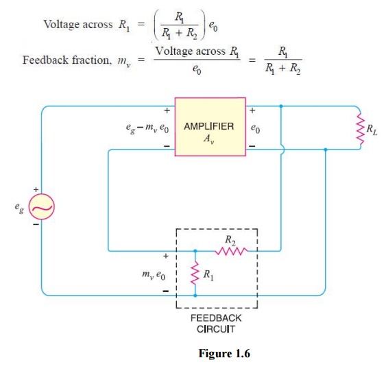
Feedback Circuit
The function of the feedback circuit is to return a fraction of the output voltage to the input of the amplifier. Fig. 13.6 shows the feedback circuit of negative voltage feedback amplifier. It is essentially a potential divider consisting of resistances R1 and R2. The output voltage of the amplifier is fed to this potential divider which gives the feedback voltage to the input. Referring to Fig. 13.6, it is clear that :
Principles of Negative Current Feedback
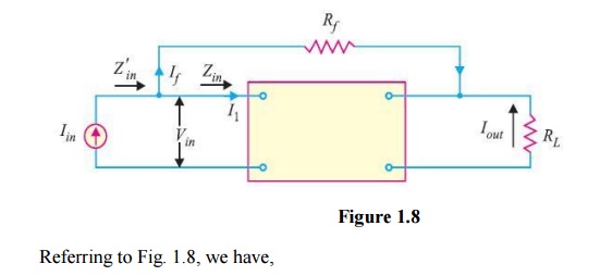
In this technique, a portion of the output current is fed back into the amplifier’s input. In other words, the feedback current (If) is inversely proportional to the amplifier’s output current (Iout). The fundamentals of negative current feedback are depicted in Fig. 1.7. Current-shunt feedback circuit is the name of this circuit. Between the amplifier’s input and output is a feedback resistor Rf. Without feedback, this amplifier has a current gain of Ai. The output circuit will display a current I1 at the amplifier’s input terminals as Ai I1, i.e., Iout = Ai I1.
Now a fraction mi of this output current is feedback to the input through Rf.
The fact that arrowhead shows the feed current being fed forward is because it is negative feedback.
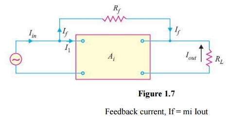
Note that negative current feedback reduces the input current to the amplifier and hence its current gain.
Current Gain with Negative Current Feedback
Referring to Fig. 13.6, we have, Iin = I1 + If = I1 + mi Iout
But Iout = Ai I1, where Ai is the current gain of the amplifier without feedback.
Iin = I1+ mi Ai I1 (ä Iout = Ai I1)
Current gain with negative current feedback is
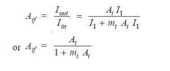
This equation closely resembles the one for the voltage gain of amplifiers with negative voltage feedback. The only distinction is that instead of dealing with voltage gain, we are dealing with current gain.
The following points may be noted carefully :
(i) The current gain of the amplifier without feedback is Ai. However, when negative current feedback is applied, the current gain is reduced by a factor (1 + mi Ai).
(ii) The feedback fraction (or current attenuation) mi has a value between 0 and 1.
(iii) The negative current feedback does not affect the voltage gain of the amplifier.
Effects of Negative Current Feedback
The negative current feedback has the following effects on the performance of amplifiers :
(i) Decreases the input Impedance
The negative current feedback decreases the input impedance of most amplifiers.
Let
Zin = Input impedance of the amplifier without feedback
Z ′in = Input impedance of the amplifier with negative current feedback
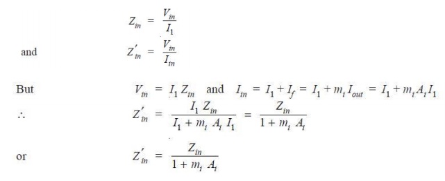
As a result, the amplifier’s input impedance is reduced by the factor (1 + mi Ai). Take note of the main distinction between negative voltage feedback and negative current feedback. The input impedance of the amplifier decreases with negative current feedback while it rises with negative voltage feedback.
Increases the output Impedance
It can be proved that with negative current feedback, the output impedance of the amplifier is increased by a factor (1 + mi Ai).
Z ′out = Zout (1 + mi Ai)
where
Zout = output impedance of the amplifier without feed-back
Z ′out = output impedance of the amplifier with negative current feed-back
The reader may recall that with negative voltage feedback, the output impedance of the amplifier is decreased.
Increases Bandwidth Feedback Amplifier
It can be shown that with negative current feedback, the bandwidth of the amplifier is increased by the factor (1 + mi Ai).
BW′ = BW (1 + mi Ai)
where
BW = Bandwidth of the amplifier without feed-back
BW′ = Bandwidth of the amplifier with negative current feedback