DC Servo Motor: Construction, Working, Its Applications
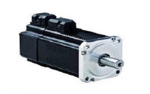
Table of Contents
One type of electrical motor used to rotate machine parts with extreme precision is a servo motor, also known as a servo. This motor has a control circuit that gives feedback on the position of the motor shaft at any given time, making it possible for these motors to rotate precisely. It is advantageous to rotate an object at a certain distance or angle using a servo motor. The two types of this motor are the AC servo motor and the DC servo motor. A servo motor is referred to as a DC servo motor if it operates on DC power, and an AC servo motor if it operates on AC power. The working with applications of the DC servo motor is covered in this tutorial.
What is DC Servo Motor?
A DC servomotor is one that generates mechanical output, such as position, velocity, or acceleration, using DC electrical input. These motors are typically used as prime movers in numerically controlled machinery, computers, and many other places where starts and stops need to be made precisely and quickly.
DC Servo Motor Construction and Working
The following block diagram shows the various components that make up a DC servo motor. Each element in this diagram and its purpose are discussed below.
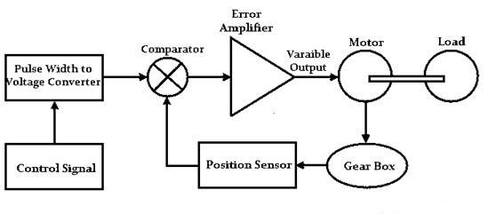
The motor used in this is a typical DC motor, complete with its separately excited field winding. So they can also be divided into armature-controlled and field-controlled servo motors depending on the type of excitation. The load in this case is a straightforward fan or industrial load that is simply connected to the mechanical shaft of the motor. Depending on the application, the gearbox in this construction functions as a mechanical transducer to change the motor’s output, such as acceleration, position, or velocity.
The primary purpose of a position sensor is to obtain a feedback signal that represents the load’s current position. Typically, a potentiometer is used to deliver a voltage that is proportional to the absolute angle of the motor shaft as it passes through the gear mechanism. A position sensor’s output and a reference point are compared by the comparator to create the error signal, which is then sent to the amplifier. There will not be an error if the DC motor is controlled precisely. The system will become closed loop thanks to the position sensor, gearbox, and comparator.
The amplifier’s job is to feed the DC motor with an amplified version of the comparator’s error. It functions as a proportional controller as a result wherever the gain is increased to achieve zero steady-state error. Depending on the feedback signal, the controlled signal provides the pulse width modulator (PWM) with input, which modulates the motor’s input for precise control if there is zero steady-state error. Additionally, this pulse width modulator generates pulses using a reference waveform and comparator.
Accurate position, velocity, or acceleration can be measured by creating a closed-loop system. The servo motor, as its name suggests, is a controlled motor that produces the desired output as a result of feedback and controller effect. The servo motor is simply driven by amplifying the error signal. These motors can be controlled better with FPGA chips or digital signal processors depending on the control signal and pulse width modulator-producing nature.
The DC servo motor rotates the shaft and gears whenever an input signal is applied to it, according to how it operates. In essence, the position sensor (potentiometer) whose knobs turn and change their resistance receives a signal from the rotation of the gears. When resistance changes, the voltage also does, changing the error signal that is fed to the controller, causing PWM to be produced.
Transfer Function of DC Servo Motor
The ratio of the Laplace transform (LT) of the o/p variable to the LT (Laplace transform) of the i/p variable can be used to define the transfer function. Typically, a DC motor converts electrical energy into mechanical energy. The armature terminals convert the electrical energy that is supplied into controlled mechanical energy.
The armature-controlled DC servo motor transfer function is shown below.
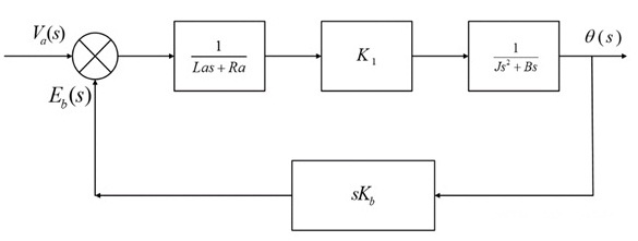
θ(s)/Va(s) = (K1/(Js2 + Bs)*(Las + Ra)) /1 + (K1KbKs)/(Js2 + Bs)*(Las+Ra)
The field-controlled dc servomotor transfer function is shown below.
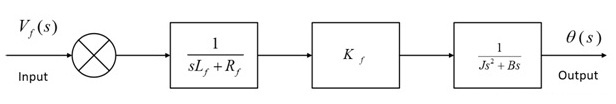
θ(s)/Vf (s) = Kf / (sLf + Rf) * (s2J + Bs)
When compared to field controlled dc servo motors, which are an open-loop system, armature-controlled dc servo motors perform better due to their closed-loop system. Additionally, the field control system’s response time is sluggish. The armature’s inductance is minimal in the case where the armature is controlled, but it is not identical in the case where the field is in control. However, while it is possible to achieve better damping in armature control, it is not possible in infield control.
Specifications
- The DC servo motor offers the following performance specifications. To properly size a motor, these specifications need to be matched based on the application’s load requirements.
- Shaft speed is simply the rate of rotation of the shaft, measured in RPM (rotations per minute).
- So Typically, the speed specified by the manufacturer is the o/p shaft’s no-load speed or the speed at which the motor’s output torque is zero.
- The motor’s terminal voltage, which also controls motor speed, is its design voltage. The motor’s voltage supply can be changed to increase or decrease this speed.
- The dc servo motor’s shaft produces the rotational force, or torque. Thus, the speed-torque characteristics of the various loads encountered within the target application serve to simply determine the required torque for this motor. These torques come in two varieties: continuous torque and starting torque.
- The required torque to start a servo motor is known as the starting torque. Usually, this torque is greater than continuous torque.
- The continuous torque is the output torque that is the capacity of the motor in constant running conditions.
- These motors must be reliable and have enough speed and torque for the application, as well as a 20 to 30% safety margin between the load requirements and the motor ratings. Cost effectiveness will be decreased when these margins are overly large.
The specifications of the 12V DC Coreless DC Servo Motor are:
- Gearbox Ratio is 64: l Planetary Three Stage Gear Box.
- Load Current is 1400 mA Power.
- The power is 17W.
- Speed is 120RPM.
- No Load Current is 75mA.
- The type of Encoder is Optical.
- The resolution of the Encoder is 768CPR of O/P Shaft.
- The diameter is 30mm.
- The length is 42mm.
- The total Length is 85mm.
- The Shaft Diameter is 6mm.
- The shaft Length is 35mm.
- The stall Torque is 52kgcm.
Characteristics
The characteristics of a DC servo motor include the following.
- The permanent magnet or separately excited DC motor and the DC Servo motor have similar designs.
- The armature voltage of this motor is managed in order to control its speed.
- High armature resistance is a design feature of the servo motor.
- It provides quick torque response.
- The motor’s speed quickly changes in response to a step change in the armature voltage.
Difference between AC servo motor and DC servo motor
The difference between a DC servo motor and an AC servo motor includes the following.
| AC Servo Motor | DC Servo Motor |
| An AC servo motor is a particular type of servomotor that produces mechanical output using AC electrical input. | A DC servo motor is one type of servomotor that produces mechanical output using DC electrical input. |
| AC servo motor delivers low output power. | DC servo motor delivers high output power. |
| These motors are adjustable for high-speed operating conditions. | These motors are adjustable for low-speed operating conditions. |
| These types of motors develop high torque. | These types of motors develop low torque. |
| The operation of this motor is stable, smooth & less noise based. | The operation of this motor is less stable, and noisy. |
| These motors have less efficiency. | These motors have high efficiency. |
| These motors have fewer stability problems. | These motors have more stability problems. |
| In these motors, there is no electronic noise problem. | In these motors, there is an electronic noise problem due to the presence of brushes. |
| The maintenance of these motors is less. | The maintenance of these motors is high because of the presence of brushes & commutator. |
| These are lightweight and in small sizes. | These are heavy & in large size. |
| These motors are appropriate for low-power-based applications. | These motors are appropriate for high-power-based applications. |
Advantages of DC Servo Motor
The advantages of DC servo motors include the following.
- These motors have much higher output power than the size & weight of the motor.
- DC servo motor operation is stable.
- This motor operation is vibration & resonance-free.
- When these motors run at high speeds then they don’t generate any noise.
- These types of motors have high torque to inertia ratio & they can pick up loads very quickly.
- They give quick responses.
- These are portable & lightweight.
- They have high efficiency.
- At high speeds, these are audibly quiet.
- The operation of Four Quadrants is possible.
The disadvantages of DC servo motors include the following.
- The DC servo motor’s cooling system is ineffective. As a result, after ventilation, this motor becomes quickly polluted.
- This motor requires regular gearing and produces its maximum output power at a higher torque speed.
- They have a complex design & need an encoder.
- These motors can be damaged by overload.
- It requires maintenance.
- These motors need tuning for stabilizing the feedback loop.
DC Servo Motor Applications
The applications of DC servo motors include the following.
- DC servo motors are used in machine tools for cutting and forming metal.
- These are employed in the positioning of antennas, printing, packaging, woodworking, textile production, twine or rope manufacturing, CMM (coordinate measuring machines), material handling, floor polishing, door opening, X-Y table, medical equipment, and wafer spinning, among other applications.
- These are applicable where high starting torque is necessary like blower drives & fans.
- So These motors are used in aircraft control systems where space & weight limitations need motors to deliver high power for each unit volume.
- These are also used mainly for robotics, programming devices, electromechanical actuators, machine tools, process controllers, etc.