Switched Reluctance Motor
Table of Contents
Switched Reluctance Motor
Switched Reluctance Motor (SRM)
The variable reluctance principle underlies the operation of switched reluctance motors. The power electronics switching circuit is used to produce the rotating magnetic field. The key idea is that the air gap determines how resistive the magnetic circuit is. Therefore, we can alter the motor’s reluctance by altering the air gap between the rotor and stator.
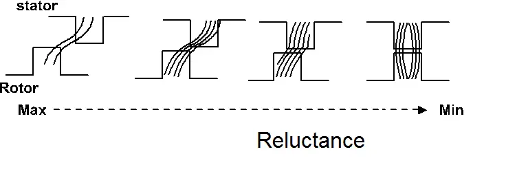
Note: Resistance to the magnetic flux is what reluctance is. (Stands against the magnetic flux. Resistance is used in electrical circuits, while reluctance is used in magnetic circuits.).
Construction of Switched Reluctance Motor
The stator and rotor of a switched reluctance motor have projected poles made of soft iron and silicon stampings. Hysteresis losses are reduced by silicon stamping.
Stator => Inward projection
Rotor => Outward projection.
The rotor does not have winding and stator only carries main field winding. Each winding in the stator is connected in series with the opposite poles to increase the MMF of the circuit. It is called phase winding. Refer to fig 1.1 AA’, BB’ and CC’.
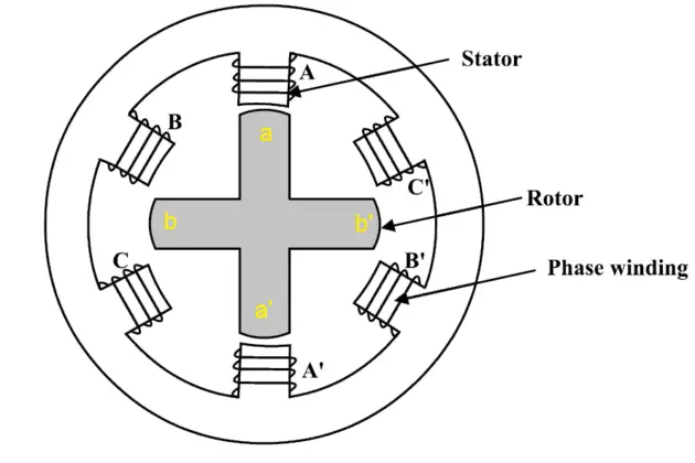
Regarding poles, the stator will have about 6 to 8 numbers of poles. But in comparison to the stator, the rotor has fewer poles. The rotor poles will range from 4 to 8. We can get a motor with a low angle of rotation by adding more poles. A position sensor is mounted on the shaft of the rotor. A control circuit uses the position sensor to determine the position of the rotor. The control circuit continuously gathers data on the position of the rotor, and then the controller provides input to the motor based on that data.
Block diagram of SRM
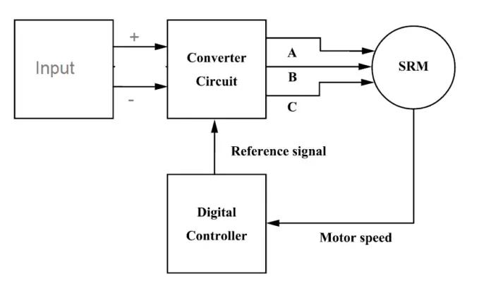
Block Diagram of SRM Fig 1.2
The motor is connected to the output of the driver/converter circuit, which is connected to the DC input. The controller circuit is connected to the feedback wire of the rotor sensor, which provides the rotor’s position in relation to the reference axis. Finally, after gathering all the data, the stator will be referred to based on that data. Additionally, the controller keeps track of the motor current to safeguard it from both internal and external problems.
Switched Reluctance Motor circuit Diagram
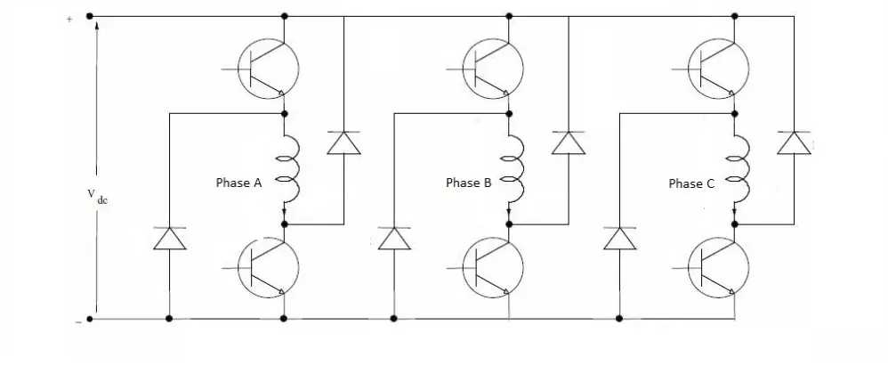
Also, note that the output of the controller is DC. And the output will be as shown in the figure 1.3.
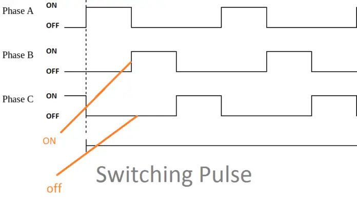
Switching Pulse of SRM Fig 1.3
Working Principle of Switched Reluctance Motor
Simplify the switched reluctance motor’s operation by using an iron piece as an example. The iron piece will align with the position of least resistance if we keep it in a magnetic field, which causes it to become magnetically locked. The switched reluctance motor operates on the same theory. The rotor’s minimum reluctance section tries to line up with the magnetic field of the stator. As a result, the rotor develops the reluctance torque.
Switched Reluctance motor Working, types
In our motor, let us consider the following notation for better understanding.
Stator Poles:
AA’ poles axis for A phase
BB’ poles axis for B phase
CC’ poles axis for C Phase
Rotor poles:
aa’ rotor poles axis for Position 1
bb’ rotor poles axis for position 2
Now the input is given to the A-phase, other B and C phase neither maximum nor minimum, then stator pole axis AA‘ and rotor pole axis aa‘ are in alignment. Ref picture Fig 1.4
So Figure 1.4 indicates that the A-phase reached the minimum reluctance position.
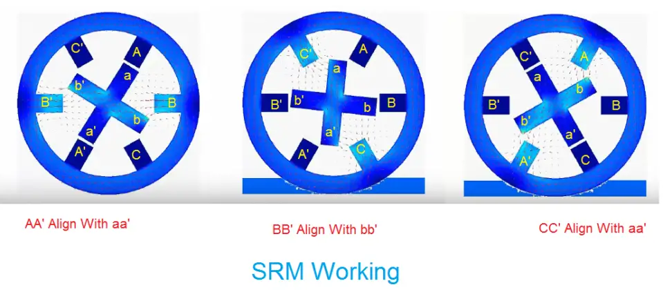
SRM Working Principle Fig 1.4
Due to the extremely small air gap between the stator and rotor and their lowest reluctance position relative to other poles. Then,
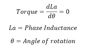
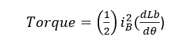
Phase A will now be switched off, and phase B will now be energised. The stator axis BB’ then turns to face the rotor axis BB’. So As shown in our diagram, move clockwise. We can quickly reverse the motor by switching its polarity. The torque is created as a result of the reluctance’s transition from maximum to minimum. The torque created is equal to
The rotor movement is depending upon the number of poles and in our case, we get 30 deg rotation by energizing one phase at a time.
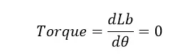
Guys here torque is nothing but a rotor movement only. When the shaft reaches to position BB’. Then there is no torque.
Now the B phase will be turned off, and the C phase will be turned on. Then the torque is developed because of rotor axis aa’ is aligned with the stator axis CC’. The rotor continues to rotate for another 30deg.
Once more, A will receive a blank stare while C is turned off. until the input power supply, the motor operates. The motor’s independent rotation can be seen in this picture. Thus Motors with switched reluctance start themselves. The control circuit keeps track of input current and motor speed continuously. When compared to the reference, if the motor speed decreases, the control assumes that a high torque is needed. To achieve the required speed, it therefore increases the input current to the motor. In such a case, the motor trips if the current exceeds the full load current.
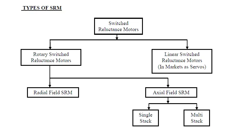
Types of Switched Reluctance Motor
Based on the construction the SRM is divided into two categories. One is linear SRM and another one is rotary SRM.
Linear SRM: Single-step Stator and rotor
Rotary SRM: More than one step stator and rotor
Advantage of Switched Reluctance Motor
- It does not require an external ventilation system as the stator and rotor slots projected. The airflow maintained between the slots.
- Since the absence of permanent magnet, such motors are available at a cheaper price.
- The rotor does not have winding since therefore no need keeps the carbon brush and slip ring assembly.
- Simple three or two-phase pulse generator is enough to drive the motor
- Self-starting and does not require external arrangements.
- The direction of the motor can be reversed by changing the phase sequence.
- Starting torque can be very high without excessive inrush currents.
- Phase losses do not affect motor operations.
- High Fault Tolerance
- High starting torque can be achieved.
- High torque/inertia ratio
Disadvantage of Switched Reluctance Motor
- Creates Torque ripple at high-speed operation
- Noise level is high
- The external rotor position sensor is required.
- Since the absence of Permanent Magnet, the motor has to designed to carry high input current. It increases the converter KVA requirement.
- At a higher speed, the motor generates harmonics, to reduce this, we need to install larger size capacitors.
Switched Reluctance Motor applications
Domestic appliances such as washing machines, vacuum cleaners, fans etc.