Slip Ring Induction Motor
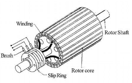
Table of Contents
Slip Ring Induction Motor
What is a Slip Ring Induction Motor?
Definition: Because the speed at which a Slip Ring Induction Motor operates is not the same as the Synchronous speed of a rotor, it is known as an asynchronous motor. This kind of motor has a wound rotor. It has a 3-phase Insulated winding circuit that is Accommodated by a Semi-closed groove at the outer edge of the Cylindrical Laminated steel core.
The rotor is wound to Correspond with the number of poles on the stator, as shown in the above figure. So A shaft is connected to the three Terminals of a rotor and the three start Terminals via slip rings. Transmission of Mechanical power is the shaft’s main function.
Construction
Understanding the slip ring Induction Motor’s construction is crucial before discussing its operating theory. So let’s start with the building, which consists of two components: the Stator and Rotor.
- Stator
- Rotor
Stator
The stator of this motor comprises of various slots that are arranged to support the construction of a 3-phase winding circuit connecting to a 3-phase AC source.
Rotor
This motor’s rotor is made up of a Cylinder core and steel Laminations. In addition, the rotor has parallel slots for 3-phase windings. These slots have windings that are 120 degrees apart from one another. This setup can minimise noise and prevent erratic motor braking.
Working of Slip Ring Induction Motor
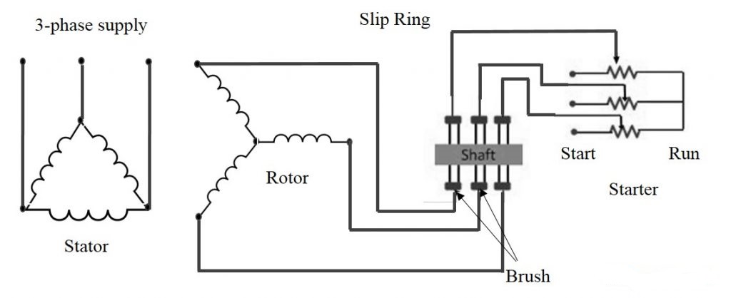
The electromagnetic induction theory of Faraday’s law underlies the operation of this motor. A stator winding generates magnetic flux when it is excited by an AC supply. So The rotor winding induces and produces a magnetic flux current according to Faraday’s law of electromagnetic induction. The torque created by this induced EMF allows the rotor to spin.
However, because the developed torque is not unidirectional, the phase difference between the voltage and current does not meet the requirements to generate high starting torque. To increase a motor’s phase difference, a high external resistance is connected to the circuit. Inductive reactance and the phase difference between I and V are consequently decreased. This reduction enables the motor to produce high starting torque as a result. The slip ring induction motor diagram is shown below.
Why Slip Rings are used in an Induction Motor?
The difference between the flux speed and the rotor speed is referred to as slip. There must be some difference between the rotor speed and stator field speed for an induction motor to generate torque. Slip is the name given to this difference. So An electromechanical device called “the Slip Ring” helps transmit electrical signals and power from a stationary source to a rotating component.
So Other names for slip rings include collector rings, swivels, electric rotary joints, and rotary electrical interfaces. Depending on the application, the slip ring may occasionally need more bandwidth to transmit data. By enhancing system performance and removing wires that hang from motor joints, slip rings increase a motor’s efficiency and performance.
Slip Ring Induction Motor Resistance Calculation
The peak torque occurs if
r = Smax. X —— (I)
Where, Smax = Slip at pull-out torque
X = Inductance of a rotor
r = resistance of rotor winding
Adding external resistance R to equation (I),
r+R= (Smax)’. X —— (ii)
From equation (i) and (ii),
R = r(S’ max/Smax – 1) —— (iii)
By definition of Smax, we get Smax = 1 – (Nmax/Ns) —— (iv)
Putting S’max =1 in equation (iii), we get
R = r. (1/Smax-1) —— (v)
Let’s say, Ns = synchronous speed of 1000rpm and pull-out torque happens at 900 rpm, equation (iv) reduces to Smax = 0.1 (i.e., 10% slip)
Substitute in equation (v),
R = r. (1/0.1 – 1)
R = 9. r
‘r’ is measured using a multimeter. The resistance value of 9 times higher than of a slip ring rotor resistance is connected externally to experience maximum starting torque.
Slip Ring Induction Motor Speed Control
The speed control of this motor can be done using two methods which include the following.
Effect of Adding External Resistance
These motors typically start up when they draw full line voltage, which is 6–7 times greater than full load current. External resistance that is connected in series with the rotor circuit can be used to control this high current. During the motor kick-off, the external resistance functions as a variable rheostat and automatically adjusts to high resistance to obtain the necessary starting current.
As soon as the motor reaches normal speed, the external resistance decreases, increasing a motor’s starting torque. Adjusting external resistance helps a motor’s power factor while also reducing rotor and stator current.
Using Thyristor Circuit
Another method for regulating a motor’s speed is through a thyristor on/off circuit. This technique involves filtering the rotor AC current before connecting it to a 3-phase bridge rectifier and external resistance. The thyristor is turned on and off at a high frequency while being connected across an external resistance. By adjusting the speed-torque characteristics, the ratio of on-time to off-time calculates the actual value of rotor circuit resistance that aids in controlling the speed of a motor.
Difference Between Squirrel Cage and Slip Ring Induction Motor
The difference between these two motors is discussed below.
| Slip Ring Motor | Squirrel Cage Motor |
| Rotor of wound type | Rotor is of squirrel cage type |
| Rotor has cylindrical core has parallel slots, in which each slot has a bar | Slots are not parallel to each other |
| Construction is complicated because of slip rings and brushes | Construction is simple |
| External resistance circuit is connected with a motor | No external resistance circuit as bars of the rotor is completely slotted |
| Starting torque is high | Torque is low |
| Efficiency is low | Efficiency is high |
Advantages and Disadvantages of Slip Ring Induction Motor
Advantages
- High and excellent starting torque to support high inertia loads.
- It has a low starting current due to external resistance
- Can take full load current that is 6 to 7 times higher
Disadvantages
- Includes higher maintenance costs due to brushes and slip rings compared to squirrel cage motor
- Intricate construction
- High copper loss
- Low efficiency and low power factor
- Expensive than 3 phase squirrel cage induction motor
Application of slip ring induction motor
Some of the applications of slip ring induction motor are
- These motors are used where higher torque and low starting current are required.
- Used in applications like elevators, compressors, cranes, conveyors, hoists, and many more