Single Phase Induction Motor
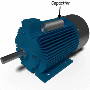
Table of Contents
This article will provide Fundamentals, description, types and working Principle of single phase Induction Motor.
Single Phase Induction Motor Construction
The rotor and stator are the two main Components of an Asynchronous motor, just like any other Electrical Motor.
Stator:
Stator is a Stationary component of an Induction motor, as its name suggests. The stator of a single phase Induction motor receives a single phase AC supply.
Rotor:
An Induction motor’s Rotating component is called the rotor. The shaft is connected to the Mechanical load by the rotor. The Single-phase Induction Motor uses a Squirrel cage rotor as its rotor.
The single phase Induction motor is built very similarly to the three phase Squirrel cage Induction motor. However, compared to a three phase Induction Motor, a single phase Induction motor’s stator has two Wndings as opposed to one three phase winding.
Stator of Single Phase Induction Motor
Laminate Stamping is used to reduce eddy current losses on the stator of the Single-phase Induction motor. On its Stamping, slots are available for carrying either the main winding or the stator. Silicon steel is used to make Stampings in order to minimise Hysteresis losses. The magnetic field is created when we apply a single phase AC supply to the stator winding, and the motor rotates at a speed that is just a little bit slower than the Synchronous speed Ns.
Synchronous speed Ns is given by

Where,
f = supply voltage Frequency,
P = No. of poles of the motor.
Except for two differences in the single phase Induction motor’s winding, the stator of a three phase Induction motor is built similarly to a single phase Induction motor.
- To begin with, concentric coils are typically used in Single-phase Induction motors. The use of Concentric coils allows us to easily change the number of turns per coil. Nearly sinusoidal describes the mmf distribution.
- Asynchronous motors, with the exception of shaded pole motors, have two stator windings: the main winding and the auxiliary winding. These two windings are arranged in quadrature with respect to one another.
Single Phase Induction Motor Rotor
The single-phase induction motor’s rotor is built similarly to the three-phase induction motor with a squirrel cage. The cylindrical rotor has slots all around its edge. The slots are slightly skewed rather than parallel to one another in order to prevent magnetic locking of the teeth on the stator and rotor and to improve the smoothness and quietness of the induction motor’s operation (i.e. less noisy).
Bars made of brass, copper, or aluminium make up the squirrel cage rotor. These copper or aluminium bars are known as rotor conductors and are inserted into the rotor’s slots on the outside. The rotor conductors known as the end rings are permanently shorted by the copper or aluminium rings.
The term “squirrel cage induction motor” refers to the complete closed circuit that results from the bracing of the rotor conductors to the end ring for mechanical support. The electrical resistance of the rotor is very low as end rings permanently short the bars, making it impossible to add external resistance. The single phase induction motor’s construction is incredibly straightforward and durable because brushes and slip rings are not used.
Working Principle of Single Phase Induction Motor
NOTE: Due to the interaction of these two fluxes, the required torque can be produced by any Electrical motor, whether it be an AC or DC motor.
Alternating current begins to flow through the stator or main winding of a single phase Induction motor when we apply a single phase AC supply to it. The main flux is an Alternating flux created by this alternating current. The rotor conductors are cut as a result of this main flux’s linkage to the Conductors.
The rotor induces emf in accordance with Faraday’s law of Electromagnetic Induction. The current begins to flow in the rotor once the rotor circuit is closed. The rotor current is the name of this flow. The flux created by this rotor current is known as the rotor flux. The induction motor got its name because it operates on the Induction Principle, which causes this flux to be produced. There are currently two fluxes: the main flux and the rotor flux. The desired torque, which the motor needs to rotate, is produced by these two fluxes.
Why Single Phase Induction Motor is not Self Starting?
The double field revolving theory states that we can divide any alternating quantity into two parts. Each component rotates in the opposite direction from the other and has a magnitude that is equal to half the maximum magnitude of the alternating quantity. For instance, a flux φ can be separated into its two components.
Each of these components rotates in the opposite direction i. e if one φm/2 is rotating in a clockwise direction then the other φm / 2 rotates in an anticlockwise direction.
When we apply a single phase AC supply to the stator winding of single phase induction motor, it produces its flux of magnitude, φm. According to the double field revolving theory, this alternating flux, φm is divided into two components of magnitude φm/2. Each of these components will rotate in the opposite direction, with the synchronous speed, Ns.
Let us call these two components of flux as forwarding component of flux, φf and the backward component of flux, φb. The resultant of these two components of flux at any instant of time gives the value of instantaneous stator flux at that particular instant.
The forward and backward components of flux are now exactly opposite one another at the initial condition. Additionally, the magnitude of both of these flux components is the same. As a result, they cancel one another, leaving the rotor at the starting condition with zero net torque. Therefore, single phase induction motors cannot start themselves.
Methods for Making Single Phase Induction as Self Starting Motor
Due to the alternating nature of the stator flux produced and the fact that its two components cancel out at startup, it is clear from the discussion above that single-phase induction motors are not self-starting. As a result, there is no net torque. Making the stator flux rotating, as opposed to the alternating type, which rotates only in one direction, will solve this issue. The induction motor will then start on its own.
We now need two alternating fluxes with some phase difference between them in order to create this rotating magnetic field. A resultant flux is created when these two fluxes interact with one another. This resulting flux rotates in space in only one direction and has a rotating nature.
We can get rid of the extra flux once the motor starts up. Only the main flux will have any further effect on the motor. There are primarily four types of single phase induction motors, as determined by the processes used to make asynchronous motors into self-starting motors:
- Split phase induction motor,
- Capacitor start capacitor run induction motor,
- Capacitor start inductor motor,
- Permanent split capacitor motor or single value capacitor motor.
- Shaded pole induction motor.
Comparison between Single Phase and Three Phase Induction Motors
- Compared to three phase induction motors, single phase induction motors are easy to build, dependable, and cost-effective for small power ratings. .
- For the same size, the single-phase induction motors develop about 50% of the output as that of three phase induction motors.
- The electrical power factor of single phase induction motors is low as compared to three phase induction motors.
- The efficiency of single phase induction motors is less compared to that of three phase induction motors.
- The starting torque is also low for asynchronous motors/single phase induction motor.
Single phase induction motors are simple, robust, reliable and cheaper for small ratings. They are available up to 5 KW rating.