Parallel Operation of Transformer
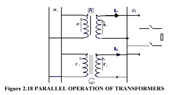
Table of Contents
Parallel operation of Transformer
Parallel Operation of Transformer
By “parallel operation,” we refer to the connection of two or more Transformers to the same Primary-side supply bus bars and Secondary-side bus bars and loads. In practice, this Requirement is Frequently seen. The following justifies the need for parallel operation.
1. Non-availability of a single large Transformer to meet the total load Requirement.
2. The power demand might have Increased over a time Necessitating Augmentation of the Capacity. More Transformers connected in parallel will then be pressed into service.
3. To ensure Improved Reliability. Even if one of the Transformers gets into a fault or is taken out for Maintenance/repair the load can continued to be Serviced.
4. To Decrease the spare Capacity. One machine can be used as a backup if many smaller size Transformers are used. A spare machine with a similar rating must be available if only one large machine is feeding the load. With fewer machines in operation at a location, the spares issue gets worse.
5. When Installation of large Transformers is Hampered by Transportation issues, it might be simpler to transport smaller Transformers to the location and operate them Simultaneously. The physical setup of two single phase Transformers operating in parallel on the primary side is shown in Fig. 37. Bus bars for input voltage are connected to Transformers A and B. They are connected to output/load bus bars after the polarities have been established. Before two or more Transformers can be connected in parallel and Successfully share a load, a number of requirements must be satisfied. They are,
1. The voltage ratio must be the same.
2. The per unit Impedance of each machine on its own base must be the same.
3. The Polarity must be the same, so that there is no Circulating current between the Transformers.
4. The phase Sequence must be the same and no phase difference must exist between the Voltages of the two Transformers.
Where,
V1=Load bus voltage
V2=Supply voltage
With reference to single phase transformers, these conditions are first reviewed, and after that, the three phase cases are covered. The turns ratio and voltage ratio are typically assumed to be the same. Even if the turns ratios are the same, a large ratio can lead to significant voltage errors. If the secondaries do not display the same voltage when the primaries are connected to the same bus bars, paralleling them would cause a circulating current between the secondaries. On the primary side, circulating current will also be reflected.
Thus, the transformers can still draw a sizable amount of current even when no load is connected, and they do so by producing copper losses. A no-load voltage difference of 1% will produce a circulating current equal to 10% of the full load current in two identical transformers with a 5% percentage impedance. When the load is connected, this circulating current is added to the load current, causing an uneven distribution of the load. In such circumstances, it is impossible for one transformer to carry the combined full load of the two transformers without the other overloading.
Impedance per unit It might be necessary to use Parallel Operation of Transformer with varying ratings. The larger machine must draw more current if they are required to distribute the overall load proportionately to their ratings. Due to their connection at the input and output ends, each machine’s voltage drop must be the same. As a result, smaller machines must have higher ohmic impedance than larger machines. The impedances must therefore be in the ratings’ inverse ratios.
Each transformer’s per-unit impedance on its own base must be the same because voltage drops must be the same. Additionally, if active and reactive powers must be distributed proportionally to ratings, impedance angles must also be equal. As a result, for proper load sharing, the per unit resistance and per unit reactance of both transformers must be equal. Connection polarity In the case of single phase transformers, the polarity of the connection can either be the same or opposite. The voltage that results must be zero inside of the loop that the two secondaries form.
The two voltages add together if the wrong polarity is selected, leading to a short circuit. With significant circulating current, permanent phase error between the phases is possible in polyphase banks. Such transformer bank connections must not be in parallel. Phase errors cannot be compensated, but the turn’s ratios in such groups can be adjusted to give very close voltage ratios. A phase error of 0.6 degrees results in a voltage difference of 1%. As a result, only polyphase transformers from the same vector group can be used in parallel. By switching the phase order of one of the transformers’ primary and secondary terminals, transformers with a 30 degree angle can be paralleled to those with a +30 degree angle.
In this manner, the phase angle error issue can be solved. Only in the case of polyphase systems does the phase sequence of operation become important. One vector group’s poly phase banks may be connected in parallel. However, a transformer with a +30 phase angle can be paralleled with one with a 30 phase angle; in this case, one of them has the phase sequence reversed at both the primary and secondary terminals. Even if two transformers are members of the same vector group, they cannot be connected in parallel if their phase sequences differ.
A phase sequence indicator can be used to determine the phase sequence. Using their equivalent circuit, the performance of two or more single phase transformers operating in parallel can be calculated. The method is the same in the case of polyphase banks, and the single-phase equivalent circuit can be applied. Essentially, two cases arise in these issues. Case A is the situation in which the voltage ratios of the two transformers are equal, whereas Case B is the situation in which they are not. These are now covered in order.